Spaces to experiment.

Explore the laboratories supporting electronics, communication, computing, design and student projects.

Explore · Build · Discover

Our laboratories

11 active facilities

Search by laboratory name or description
1
Department laboratory

BASIC ELECTRONICS ENGINEERING LABORATORY

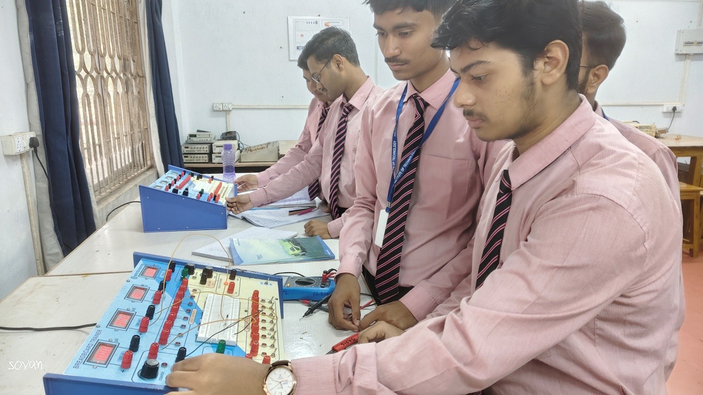
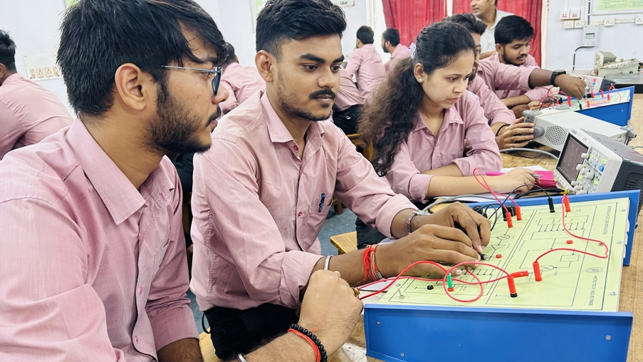
As the name suggests, it is the very beginning part in the practical area for all engineering disciplines. According to the syllabus designed by HIT (Autonomous), 1st & 2nd semester students become familiar with basic components of analog and digital electronics. They gather knowledge through the observation of the actual behavior of electronic components. Ten numbers of equal timing slots in a week are available where 40 students can perform experiment at a time with 10 no of experimental setup in equal batch sizes. Several no of faculties and instructors/demonstrators associated with this lab continuously look over to assist students with full enthusiasm.

View laboratory details
2
Department laboratory

ELECTRONICS DEVICE LAB

This manual is your guide to the second electronics laboratory in the electrical engineering program. It is assumed that by completing the first electronics laboratory course you are familiar with basic electronic measurements and instrumentation, as well as with elements of data analysis, presentation of results, and reporting. These elements will be still emphasized and further developed in this laboratory. Professional engineering practice requires using proper experimental methods and procedures. They include not only good measurement techniques, but also proper recording of all relevant information, preparing tables and graphs, etc. Almost as important as obtaining good data is their proper presentation which often determines success in this laboratory course as it does in engineering practice. Upon completion of the second laboratory course you should be very familiar with effective laboratory practices and professional style data presentation. They will be a great asset in your future.

View laboratory details
3
Department laboratory

MICROPROCESSOR & DIGITAL ELECTRONICS LABORATORY

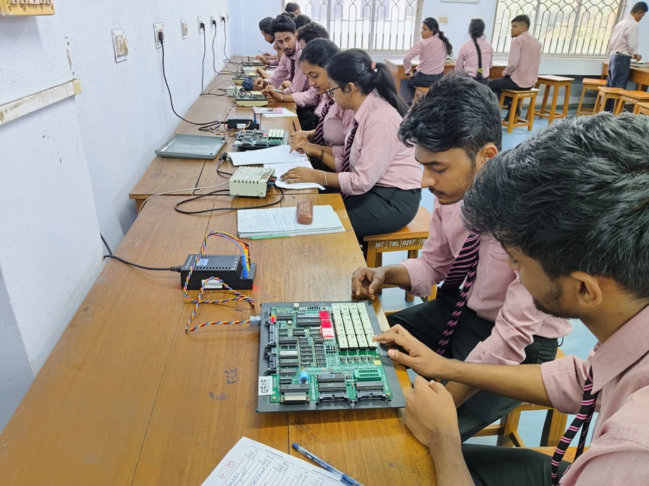
It is one of the core laboratories to acquire knowledge of Digital System design for the students of the ECE department. According to the syllabus prescribed by BOS, ECE of HIT, 3rd semester students design different logical, combinational and sequential circuits and observe their results. They gather knowledge by the various method of designing a circuit. They can compare resemble of a circuit with constructed truth table. Ten numbers of equal timing slots in a week are available where 40 students can perform experiment at a time with 20 no of experimental setup in equal batch sizes. In 4th semester students of the department of ECE perform various programming experiments upon 8085, 8086 microprocessor and 8051 microcontrollers. Several no of faculties and instructors/demonstrators associated with this lab continuously look over to assist students with full enthusiasm.

View laboratory details
4
Department laboratory

MICROWAVE ENGINEERING & ANTENNA LABORATORY

In this era of high-speed communication, RF Engineering is one of the major areas of interest. For understanding the wireless communication in the microwave frequency bands this lab provides the fundamental background. Equipment available in this lab provides sufficient facility to carry out the related labs mentioned in the course curriculum and also research facilities for the undergraduate students.

View laboratory details
5
Department laboratory

COMMUNICATION SYSTEMS LABORATORY

The Communication Systems Laboratory is employed for undergraduate students of the institute. It is primarily used for conducting the Analog Communication Lab (EC-491) during the 4th semester and the Advanced Digital Communication Lab (EC-593) in the 5th semester. Additionally, the lab offers extended facilities for interested undergraduate and postgraduate students to carry out project work related to communication systems.

View laboratory details
6
Department laboratory

DIGITAL SIGNAL PROCESSING & CONTROL SYSTEM LAB

Digital Signal Processing and Control System Lab abbreviated as DSP & CONTROL Lab is employed for the under-graduate students of our college. The post-graduates use it as a Project Lab while the under-graduates utilize it for working with MATLAB R2023b and DSP processor .This lab is facilitated for the students in their fourth semester as Control System and Instrumentation Lab and fifth semester as Digital Signal Processing Lab.

View laboratory details
7
Department laboratory

IOT & ROBOTICS LAB

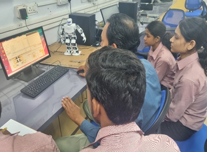
IOT & Robotics Laboratory has been established in the year of 2024, Department of Electronics and Communication Engineering . The IOT and Robotics Lab is a dynamic space designed to foster innovation, experimentation, and hands-on learning in the fields of Internet of Things (IoT) and robotics. The lab is equipped with modern tools and development kits such as Arduino, Raspberry Pi, various sensors, actuators, and robotic kits that allow students and researchers to build and test intelligent systems. The primary objective of the lab is to bridge theoretical knowledge with practical implementation, enabling students to develop smart devices, automation systems, and robotic applications. Projects in the lab often involve wireless communication, real-time data monitoring, machine learning integration, and autonomous robotics. This lab provides a platform for interdisciplinary collaboration and encourages students to work on real-world problems in areas such as home automation, health monitoring, smart agriculture, and industrial automation. Through workshops, competitions, and guided research, the IoT and Robotics Lab plays a crucial role in shaping the next generation of engineers and innovators.

View laboratory details
8
Department laboratory

VLSI DESIGN & SIGNAL PROCESSING LAB

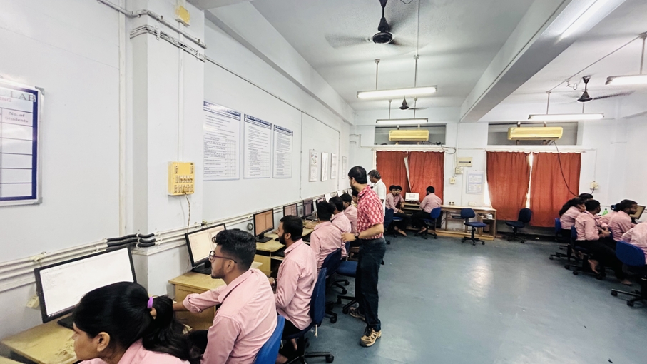
VLSI DESIGN & SIGNAL PROCESSING LAB is well equipped with the standard VLSI EDA tools and hardware resources. The lab facility includes course lab for course projects, assignments and research. This Lab consists of total 22 good qualities PC with power backup. The focus of this lab is widely spread towards different pros and cons of the entire upgrading VLSI domain and Signal Processing domain. Development works at different levels like digital VLSI simulation, circuits & system design and research in some recent trends like advanced communication systems have been extensively being carried out.

View laboratory details
9
Department laboratory

PROJECT LAB

The project laboratory is pivotal in enhancing practical skills for future employment of engineering students and facilitates immersive life-long learning. It is the place where students can enhance their educational expertise. As per the ongoing tradition of this department, the students are always encouraged to gain hands-on expertise in various fields of Electronics and Communication Engineering. As per the guidelines of BoS members, AICTE curriculum and NEP 2020 guidelines, the Department has introduced hands-on projects during the last 4 semesters (5th to 8th). In the 5th semester, students utilize the knowledge they gained from the previous 4 semesters to develop discrete component-based devices like power supply units, communication transmitters and receivers, etc., and are evaluated on a performance basis for Mini Project Lab 1.As the students gain expertise with discrete components, they are introduced to more advanced kits and IC-based projects involving various departmental labs, including the newly introduced IoT and Robotics lab. The students are evaluated based on their performance for Mini Project-2 in the 6th semester. Several training programs, internship programs, and invited talks are carried out to meet the advanced industrial requirements in the contemporary scenario.

View laboratory details
10
Department laboratory

PCB & PROTOTYPE DESIGN LABORATORY

This is an extracurricular lab under the department of ECE. Apart from departmental labs according to the syllabus designed by HIT (Autonomous) for undergraduate and postgraduate students this is an additional lab for the purpose of design and development of PCB. Using this extra facility students can develop their project related PCBs, any kind of self motivated work upon PCB design and development of electronic circuits in any competetional area. Here three methods are used to develop PCBs namely ‘UV exposed’ method, ‘Silk screen’ method and ‘Manual’ method. Experienced and well expert Instructors, Demonstrators ensure of making fine track PCBs (single sided and double sided). In recent past years ECE department organized several winter schools upon PCB design in batches with lot of participants from inside and outside campus.

View laboratory details
Department laboratory

COMPUTING AND RESEARCH LAB

This Lab was established in 2024 with the primary goal of significantly enhancing the research capabilities of the department. It aims to support 3rd year and 4th year B. Tech students in developing and executing their major project work. This initiative aligns closely with the department's mission and vision, which emphasize fostering a culture of innovation, encouraging interdisciplinary research collaborations, and upholding the values of technical excellence in the rapidly evolving field of computer science and engineering. The lab serves as a hub for creativity, facilitating advanced experiments and providing students and faculty with the necessary infrastructure and environment to pursue cutting-edge research and development.

View laboratory details

Previously listed facilities

1 archived

12
Archived facility

ANALOG ELECTRONICS & DESIGN LAB

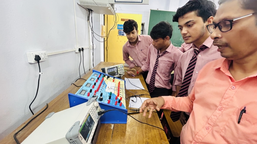
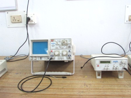
Name of the Important Equipment General Purpose Breadboard Trainer Kit-10Nos Function Generator-5Nos, CRO-4Nos, Multi meter-15 Nos, PC- 1 Nos Projects in third year courses and during the final year are also built and tested in this lab. Equipment includes Digital oscilloscopes, digital multimeters, function generators, power supplies.  Analog Electronics Lab experiment (ECE-394), Circuits Design Lab experiment (ECE-883), and Final Year Projects are instructed in this lab. The objective of this laboratory is to link the theoretical concepts of different analog electronics circuits with practical feasibility thereby giving them a scope to learn basic electronics circuits and their different electrical characteristics in a better way. List of the Major Equipments:- General purpose trainer kit Function generator Synthesized Function generator Cathode Ray Oscilloscope (CRO) Digital Storage Oscilloscope (DSO) Digital Multimeter. Voltmeter Active and passive component. List of the Components:-        Resistor        Capacitor        FET       Transistor List of Experiments for Analog electronics &circuit Lab (EC-394) Study of diode as clipper & clamper. Study of Zener diode as a voltage regulator. Study of ripple and regulation characteristics of full wave rectifier without and with capacitive filter. Study of characteristics curve of BJT & FET. Construction of a two stage RC coupled amplifier & study of it’s gain & bandwidth. Study of class A & class B power amplifiers. Study of class C & push pull amplifiers. Realization of current mirror & level shifter circuit using operational amplifier. Study of timer circuit using NE 555& configuration for monostable & astable multivibrator. Construction & study of bistable multivibrator using NE555. Study of switch Mode Power Supply & construction of a linear voltage regulator using regulator IC chip. Construction of a simple function generator using IC. Realization of a V-to-I & I-to-V converter using Op-amps. Realization of a Phase Locked Loop(PLL) using Voltage Controlled Oscilator. Study of DAC & ADC.    List of Design Problems for Design Lab (EC-883)       Power supply Design a regulated voltage source (Load current 50mA) using a Zener diode (having test current 20mA) as a simple shunt regulator with simple capacitive filter and    (a) Half wave rectifier circuit (b) Full wave rectifier circuit (c) Bridge rectifier circuit                       (i) 5V (ii) 7V (iii) 9V (iv) 12 V Design a regulated voltage source (Load current 50mA) using 78XX or 79XX with (a) Half wave rectifier circuit (b) Full wave rectifier circuit (c) Bridge rectifier circuit                       (i) 5V (ii) (ii) 12 V (iii) -5V    (iv) -12 (v) -15v Design a split power supply using 78XX & 79XX        (i) +/- 5V      (ii) +/- 12V         Voltage Amplifier and Oscillator Design a small signal voltage amplifier using a BJT in CE mode in fixed bias with collector current Ic=1mA having voltage gain Av (a) 50 (b) 60 (c) 70 (d) 80 (e) 75 (f) 85 (g) 90 (h) 55 (i) 65 (j) 95 Design a small signal voltage amplifier using a BJT in CE mode in self bias with collector current Ic=1mA having voltage gain Av (a) 50 (b) 60 (c) 70 (d) 80 (e) 75 (f) 85 (g) 90 (h) 55 (i) 65 (j) 95 Design a Wien bridge oscillator using OPAMP having frequency of oscillation fosc  (a) 500Hz  (b) 1KHz  (c) 2KHz  (d) 3KHz (e) 1.5KHz (f) 2.5KHz (g) 3.5KHz               Filter Design a 1st order low pass Butterworth filter having cutoff frequency fc and pass band gain Av are given below          (a) fc = 5KHz,  Av= 2  (b) fc = 10KHz,  Av= 2  (c) fc = 2KHz,  Av= 2  (d) fc = 5KHz,             Av= 3  (e) fc = 10KHz,  Av= 3   (f) fc = 2KHz,  Av= 3 (g) fc = 5KHz,  Av= 3          (h) fc = 7KHz,  Av= 2  Design a 1st order high pass Butterworth filter having cutoff frequency fc and pass band gain Av are given below           (a) fc = 500Hz,  Av= 2  (b) fc = 1KHz,  Av= 2  (c) fc = 2KHz,  Av= 2  (d) fc = 500Hz,             Av= 3  (e) fc = 1KHz,  Av= 3  (f) fc = 2KHz,  Av= 3 (g) ) fc = 3KHz,  Av= 3           (h) fc = 700Hz,  Av=2 Design a 2nd order low pass Butterworth filter having Av =1.586 cutoff frequency fc           (a) fc = 5KHz (b) fc = 10KHz (c) fc = 2KHz (d) fc = 7KHz(e) fc = 6KHz(f) fc = 8KHz                 (g) fc = 9KHz(h) fc = 4KHz Design a 2nd order high pass Butterworth filter having cutoff frequency fc          (a) fc = 500Hz (b) fc = 1KHz (c) fc = 2KHz (d) fc = 3KHz (e) fc = 4KHz (f) fc = 5KHz          (c) fc = 6KHz (g) fc = 7KHz (h) fc = 8KHz Design a 2nd order high pass filter having cutoff frequency fc and pass band gain Av are given below            (a) fc = 2KHz, Av= 5  (b) fc = 5KHz, Av= 3 (c) fc = 6KHz, Av= 4 (b) fc = 3KHz, Av= 6                                        Multivibrator Design an astable multivibrator of output frequency f and duty cycle D are given below           (a) f = 2KHz, D = 50% (b) f = 2KHz, D = 60% (c) f = 2KHz, D = 70%  (d) f = 1KHz,           D = 50%   (e) f = 1KHz, D = 60%        (f) f = 1KHz, D = 70%  (g)   f  =   1KHz,            D   = 70% (h)   f   =  1KHz,   D  =  70%   Design a monostable multivibrator of output pulse width tp          (a) 1ms  (b) 2ms  (c) 3ms  (d) 5 ms  (e) 8ms  (f) 10ms (g) 6ms (h) 12ms          Digital Circuits Design a Synchonous counter using JK Flip flops which follows a sequence 0 – 2 - 4 – 6 -8- 0 – 2 - ………-8 1 – 3 -5 -7- 9- 13 – 1………..- 13 0 – 7 -2 -5 -9 -13-0-…………-13 6 – 3-5-0- 2- 6 -3……………..-2 5 – 3 -7- 9- 13 –1…………..- 13 1 – 7 -2 -5 -9 -0-………………-9       2. Design a Synchronous counter using JK Flip flops which counts in the sequence 0 – 2 – 4 -6 -0 -2-………….-6 ; 2-4-6-8-2-4-6-8……………..: ; 4-6-8-10-4-6-8-10.      If the Mode Control unit M=0. During this count if the circuit falls into an Odd Count then it returns to the count Zero.When M = 1, then the count sequence will be       a)1-3-5-7-1-…….-7. b) 3-5-7-9……….. c) 5-7-9-11……… During this count if the circuit falls into an Even  Count  then it returns to the count One. Design and Implement a BCD to Seven Segment Display (CA type) to show 0,2,4. 1,3,5. 2,4,6. 3,5,7 4,5,6 5,6,7. 0,4,7 1,5,7       4. Design a Synchronous counter using JK Flip flops. Mod6 Mod4 Mod5 Mod7 Mod8 Mod9 Mod11 Mod12 Mod13

View laboratory details

Descriptions and images are shown from department records. Review the current equipment and facility details through the editor workflow.